Our Flugtag
Our design was inspired by a TV show we all loved watching as kids: Avatar The Last Airbender. The shows main protagonist - Avatar Aang - carries a glider that he uses as a means to fly via his ability to control the flow of air around the glider.
Since the Flugtag competition is all about combining sustained flight with creative designs, we chose his glider as the inspiration for our craft. Below is an image of the glider from the show.

In the show Avatar the Last Air Bender, Aang is the master of all four elements Air, Water, Fire, and Earth. Unfortunately we don't have the ability to manipulate the flow of air like Aang, so we had to make alterations to the design of his glider to maximize the distance we travel on the day of the competition.

Final Design

Glider

Material List
I'm a paragraph. Click here to add your own text and edit me. It's easy.

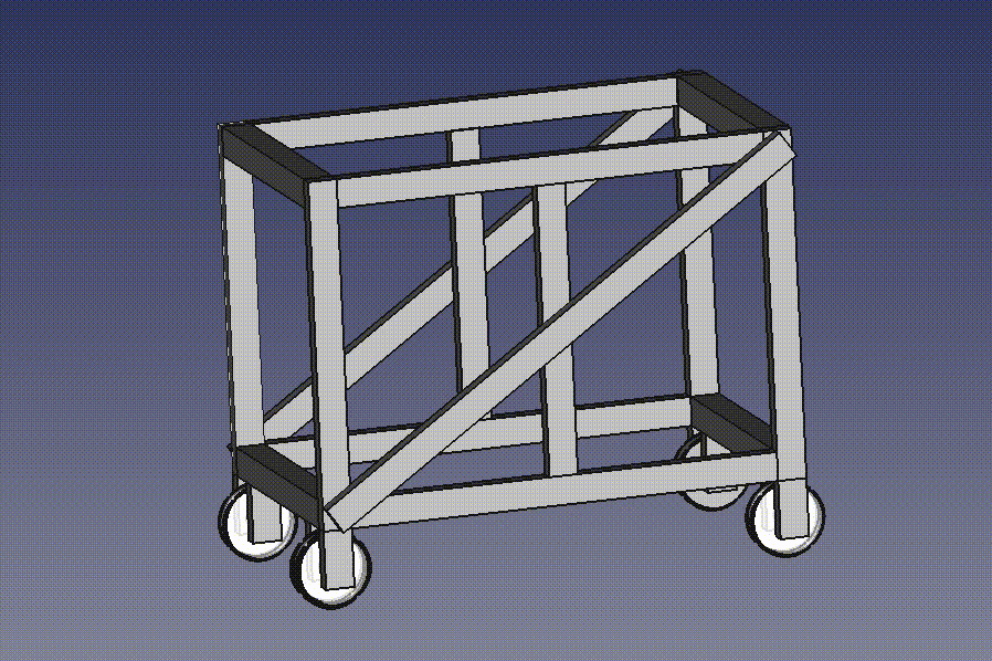
Base
Material List
Materials list

Airfoil Design

The inspiration behind our airfoil was the NACA 2415 airfoil. After researching recent successful Flugtag designs, we noticed many of them based their airfoils off the NACA 2415. This airfoil is particularly good at generating lift at low speeds, which is essential in the Flugtag competition.
Achieving a maximal lift to drag ratio (L/D) was the driving force behind the modifications we made to the NACA 2415 design. Using NASA's FoilSim program, we were able to customize the shape of our airfoil while seeing how the changes we made would affect the airfoils performance. Our final airfoil design in FoilSim design can be seen on the right.
Below are some of the final specs of our custom airfoil design:
- Angle: 0.5 degrees
- Camber %: 4.9
- Thickness % crd: 15
- L/D ratio: 9.352

I - Beam

As we have mentioned in the other sections of this website, minimizing the weight of our craft was an extremely important engineering factor to consider in our design.
We decided to use an I-beam for the central body of our glider to minimize weight while providing maximal resistance to bending moments.

Beam Connections

OUR FIRM
Our stress analysis revealed the points of maximum stress on the craft would be at the connections between the wings and the I-beam. To ensure our craft could handle the stress loads, we designed reinforced beams at the connecting points.
Outer Tube

Inner Tube

The beams overlap for 4 in. on each side of the I-beam, and are reinforced by a bolt that holds them in place.